
Mold Filling Simulation in SOLIDWORKS Plastics

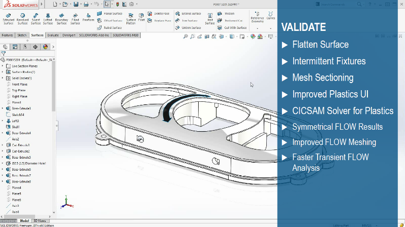
Injection molding is an efficient manufacturing process for producing high-volume, low-cost parts. Advances in polymer technology have enabled replacement of structural metal components with injection molded fiber reinforced materials. Advances in machine automation have driven per-part cost down even further, but the mold tooling required for part production remains a significant capital expense.
Mold filling simulation allows for verifying part design before mold tool steel is ever cut—ensuring that major revisions will not be necessary to either the part or the molds. Incorporating a CAD-embedded molding simulation software enables designers to make decisions to improve moldability early on and throughout the design process.

Figure 1. Fill analysis in SOLIDWORKS Plastics.
SOLIDWORKS Plastics is an add-in product for SOLIDWORKS that enables simulations for plastic injection molding and is available in three levels: ranging from Plastics Standard for predicting single part mold filling and common defects; Plastics Professional which allows analysis of the pack or “pressure hold” cycle, more complex materials and multi-cavity molds; to Plastics Premium, which enables molders and tool designers to simulate cooling channel design and predict warpage.
This article will examine some of the common molding defects that can be predicted and avoided using SOLIDWORKS Plastics—as well as the setup process required to perform an analysis.
Creating a Plastics Fill Study
Creating a Plastics study is a straightforward process, beginning with loading the SOLIDWORKS Plastics add-in.
Geometry Preparation
Geometry preparation involves making sure you are working in the SOLIDWORKS Part environment. For single parts there is no work required, but multi-cavity layouts may require conversion from assemblies into multi-body parts.
Note that for Plastics analysis the “positive” volume of the net molded part is required, rather than the negative shape of the mold cavity. If you are working from mold tooling and do not have the shape of the target part, it can easily be extracted using the Intersect feature in SOLIDWORKS.
The last task before beginning analysis setup is to define areas for the gate or injection locations where polymer will be injected into the cavity. This is commonly defined as a simple sketch point coincident with an edge or face of the model.
Study Setup
At this point a new study can be created. For most studies, the only choice the user needs to make is Solid or Shell mesh. We will explain meshing later in detail but the short version is that a Shell mesh allows rapid analysis of relatively constant wall thickness in thin-walled parts, while Solid mesh has an increased solve time but offers more rich results with less assumptions.
Figure 2 below illustrates the Plastics Study feature tree after mesh generation. The injection location was specified under boundary conditions and a sketch point was specified. The polymer was chosen inside the Injection Unit options.

Figure 2. Plastics study tree.
Starting with the 2020 version of SOLIDWORKS Plastics the user-interface was re-structured to match other SOLIDWORKS Simulation products more closely.
Like SOLIDWORKS Simulation and Flow Simulation, the study setup is stored on the part file and can take advantage of multiple configurations for analyzing geometry variations. Results files are saved in the same folder as the CAD files by default.
The Injection Units settings let you specify the polymer as well as fill settings such as injection pressure, mold temperature and fill time, if known. In the absence of user-specified parameters here, Plastics will use data from the material specifications for mold temperature as well as automatically calculated values for fill time.
For a more detailed guide on how to set up a study in SOLIDWORKS Plastics check out this video: SOLIDWORKS Plastics: Simulation Setup Guide.
Interpreting Results
A variety of part-level defects can be identified easily with Plastics Standard, which has automatic checks and visualization for short shots (incomplete fills), weld (knit) lines, sink marks and air traps in the model. Therefore, most severe molding problems can be identified and mitigated early with a quick first-pass analysis, often set up and run in just a few minutes.
Machine selection can also be considered by predicting the clamp tonnage and pressure required to mold the part.
Cooling time is estimated at this stage and part design changes can be made to reduce cooling time or minimize knit lines or sink marks.
Testing Geometry Variations
Once the initial analysis has been performed, analyzing different geometry variations or polymers is as simple as clicking the “Duplicate Study” button to create a new SOLIDWORKS configuration and copied Plastics study.
Alternatively multiple geometry variations that are prepared in advance can be set up and batch solved through the Batch Manager.
Runner Balancing
Plastics Professional adds the ability to represent multi-cavity molds. Especially troublesome for molders are “family molds” (where multiple different parts are grouped together to save on tooling cost) which can suffer from unbalanced fill times. Observe Figure 3 below, where due to their different volumes the smaller part fills much more quickly. In the pack cycle, this may result in excessive flashing and other issues.

Figure 3. Family mold prior to runner balancing.
The process of “runner balancing” or resizing the runners is normally a manual undertaking to attempt to even out the flow between disparate parts. SOLIDWORKS Plastics Professional automates this process using a runner balancing wizard which iterates and attempts to automatically optimize runner and gate sizes until equal fill rates are achieved.
Runner systems in general can be quickly prototyped using single line sketches and assigning profiles and sizes, or they may be modeled in more detail by creating a solid body to represent the runner system and flagging it as part of the runner domain.

Figure 4. Runner system: sketch lines (left) vs solid body (right).
Modeling a solid body to represent the gate and runner is the preferred method to accurately represent localized gate effects and test different gate designs such as submarine gate, cashew gate, etc.
Solid Mesh
The examples thus far have featured a shell mesh—which is appropriate for initial predictions of fill performance on thin-walled parts.
For parts that may feature thin and thick regions, or out of desire for more accuracy and rich results, it may be desirable to utilize a solid mesh.

Figure 5. Solid mesh and boundary layer element closeup.
The shell meshes only the interior and exterior faces and performs extra calculations to interpolate what the flow front is doing through the thickness of the cavity.
The solid mesh generates boundary layer elements on the inner and outer skins of the model and then fills in the inside with tetrahedral elements, which allows it to calculate the flow front explicitly.
This means that in addition to ensuring accuracy, solid mesh enables additional results outputs.
Isosurface plots allow visualizing the 3D flow front of polymer, as visible in Figure 6 below.

Figure 6. Isosurface display for fill time plot with solid mesh.
The presence of “through thickness” elements also means that accurate cut plots can be created and data can be probed at any location internal to the part, which is practically a requirement for parts that feature thick wall sections.
Solid mesh functionality is available even in Plastics Standard but only for single body parts.
Solid Mesh Performance
Despite requiring many more elements, solid mesh solvers are very well multi-threaded. Despite the speed advantage shell mesh may have in terms of solve time on lower-end hardware, the gap in solve time can be reduced on hardware taking advantage of a high number of cores in the CPU and GPUs.
Overmolding
Figure 5 and Figure 6 also show an example of insert overmolding, a feature which requires Plastics Professional. The ability to specify multiple different domains makes it easy to separate the runner body, the insert and the part cavity itself.
By including the insert in the analysis, the appropriate material can be applied and more accurately represent the thermal effects in the mold.
Plastics Professional also supports multi-shot injection molding for plastic-on-plastic parts, as well as materials such as TPU and TPE for soft-touch overmolding.
Mold-level Analysis: Cool & Warp
At the high end of SOLIDWORKS Plastics simulation in Plastics Premium, mold-level analysis can be performed by representing the runners, cooling channels and a mold body around the cavity.
Figure 7 below shows the cooling channels, defined in this case using simple sketch lines. Flow rates and a fluid are input to the cooling channels, which will perform a fluid dynamics calculation to determine their heat removal performance.

Figure 7. Cooling channel and runner system defined in Plastics Premium.
Cooling channels can also be modeled using solid bodies to represent more complex cooling, such as conformal cooling channels.

Figure 8. Virtual mold mesh cross section.
Figure 8 shows a cross section of the virtual mold—a volume of metal to represent the mold body. The mold could be represented as separate solid bodies and inserts for more complex scenarios.
Including the detail of the mold and cooling channels allows a molder or tool designer to simulate the cooling portion of the mold cycle using Plastics Premium.
Mold Temperature Assumptions & Cooling Analysis
Note that all the analyses possible in Plastics Standard & Professional are predicated on a “uniform mold temperature” assumption—meaning that the mold temperature specified is assumed to be uniform throughout. This is usually a reasonable assumption for parts with uniform wall thickness but the more non-standard the part design the higher the odds that assumption is invalid.
In any case, running the cool analysis provides much more detail. The cool analysis can be performed up front (even before Fill or Pack) which makes for a convenient workflow if the tooling designer is simply trying to optimize cooling channels.

Figure 9. Cool results – mold temperature.
Once the cooling results are available, as visible in Figure 9 above, they will automatically be incorporated into subsequent calculations such as Flow, Pack and Warp, increasing their accuracy.
Running Cool/Flow/Pack/Warp provides the most rich results the software is able to offer. Warpage is predicted and contribution of thermal versus viscous effects can be evaluated.

Figure 10. Warpage result (exaggerated deformation).
An exaggerated warp deformation is visible in Figure 10 above. If it is not possible to correct the warp by improving the part or tooling design, the inverted shape of the warpage may be exported using the Reverse Warp option when creating a deformed body. This allows exporting a shape with “windage” with the intent of cutting the reverse-warped shape into the mold to help improve accuracy of the final part.
Conclusion
SOLIDWORKS Plastics add-in allows a mold filling simulation from within SOLIDWORKS. For part designers, Plastics Standard represents a great value and will typically make moldability problems obvious with a quick “first pass” analysis.
Overmolding, family molds and an expanded range of molding processes are available in Plastics Professional. Plastics Premium adds the ability to represent cooling system design and the mold itself, as well as performing warpage analysis.
Aside from helping avoid costly tooling challenges, having a plastics simulation tool on hand is especially helpful whenever the part design veers from normal or known, tried and true existing designs. Plastics simulation allows for design innovation, rather than playing it safe, giving engineers confidence and security that approaches that of “tried and true” designs.
For more about the benefits of simulation, check out the whitepaper Enhancing Data Management Workflows Through CAD-Integrated Simulation.