Improving the Racetrack Performance of a Corvette with Custom Aero Parts
With contributions from Joe Galliera.
As both an avid car enthusiast and an engineer, the chance to improve the aerodynamics of a heavily modified C5 Z06 Corvette had the engine in my brain racing at the redline in top gear.
I routinely attend my local Cars & Coffee on Saturday mornings, which is where I was introduced to Mike Gwyn, the owner of the C5 Z06. While talking over geeky car specs, he learned that I worked for TriMech, a SOLIDWORKS reseller in the area, and that I had years of experience with 3D design and scanning. Mike is also an engineer in the metals casting industry and has some familiarity with SOLIDWORKS. He challenged me on how we might improve his Corvette’s performance on the track by adding front wings, known as canards, and a large rear spoiler. These additions aim to improve downforce, consequently enhancing the car’s handling and performance on the curves on both the track and through the winding mountain roads that he frequents.
I proposed a collaboration with my friend, “Flow Joe” Galliera, to conduct aerodynamic studies using computational fluid dynamics (CFD). Needless to say, Mike was gung-ho for the project.
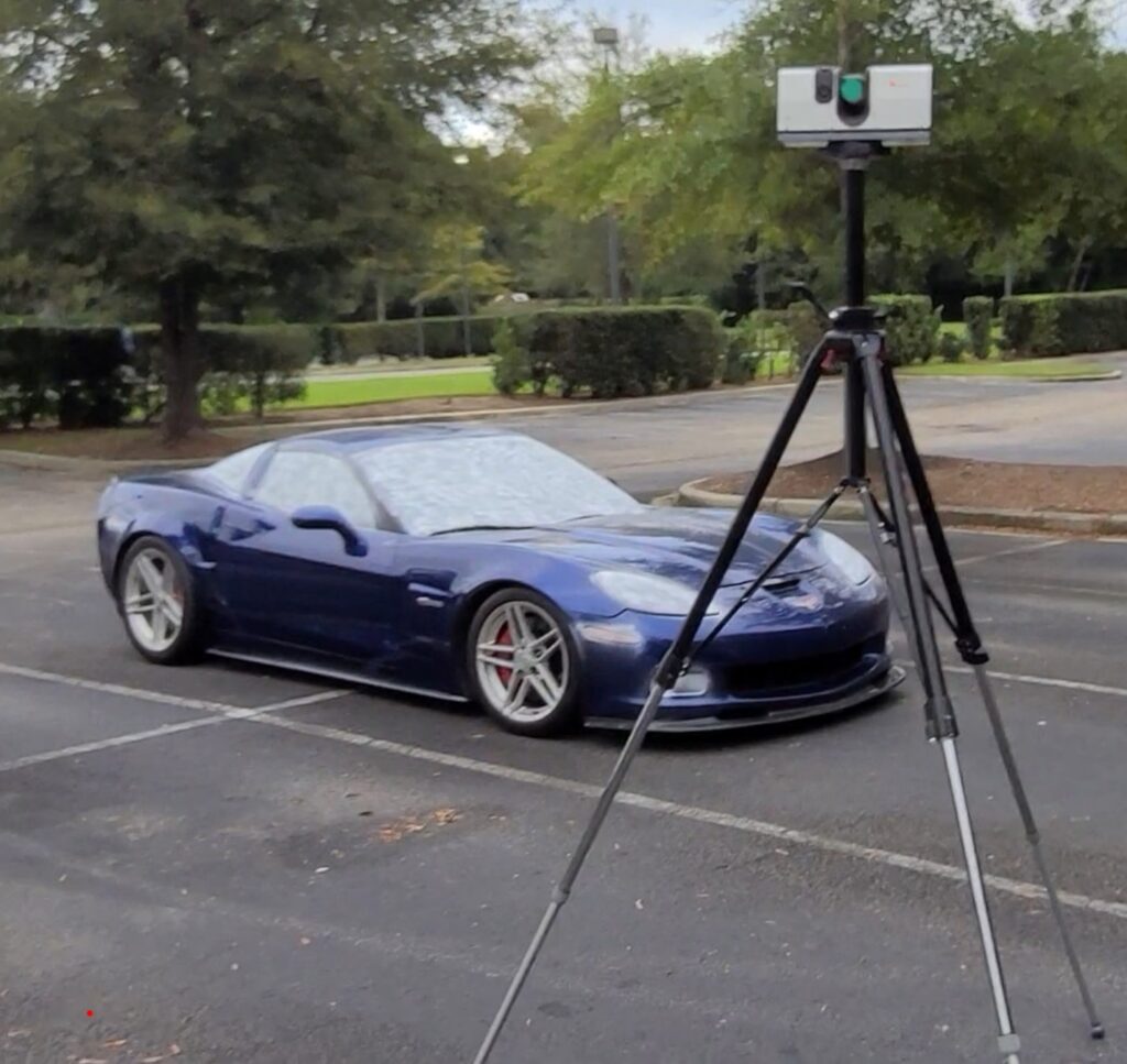
Image 1. The Artec3D Ray LIDAR scanner on a tripod next to the C5 Z06 Corvette in a parking lot.
Before anything aerodynamic could be added to the car, a 3D digital representation of the exterior of the car was required. I was grateful for the access to an Artec3D Ray LIDAR scanner. The scanner sits high atop a tripod (see image 1) in the parking lot where I met Mike with his Corvette.
Since the laser would pass through the glass, a white powder spray was applied to the windshields, headlights and taillights to ensure they could be captured. The whole scanning process, moving the tripod to eight locations around the car, took a total of about one and a half hours.
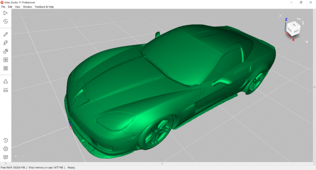
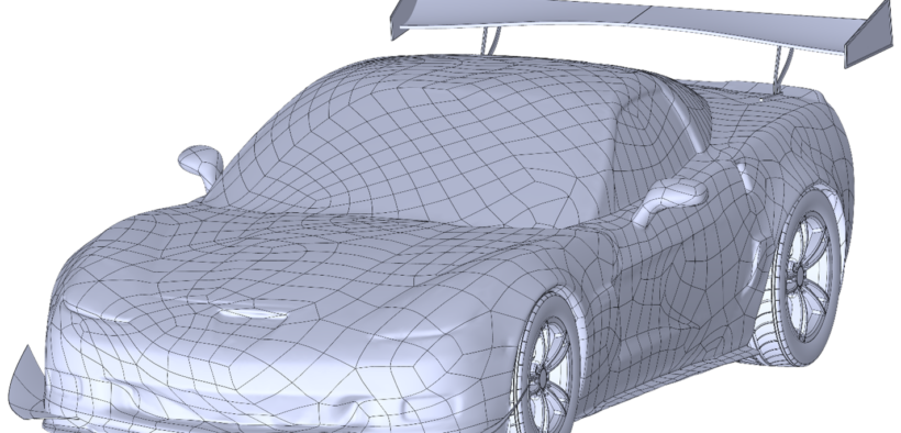
Image 2. The post-processed polygon mesh of the scanned car in Artec Studio 17 Professional.
Just over a million polygons were gathered and post-processed in Artec Studio 17 Professional (see image 2). Because there’s too much data for other downstream processes, the data was first decimated before generating an STL (Standard Tessellation Language) file. The main advantage of the STL file format is its prevalent use, but it lacks small file size and is not computationally efficient for the smooth curved surfaces found on a streamlined sport car.
An observation about the STL format that Joe likes to recount from the COFES 2017 conference is: if the creator of the STL file format knew at the time how widely it would be used in the future, he would’ve spent more than a weekend developing it. Moreover, an STL mesh has very many faceted faces and while some CFD packages can work directly with STLs, our choice of CFD tools requires solid models.
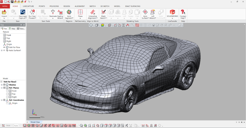
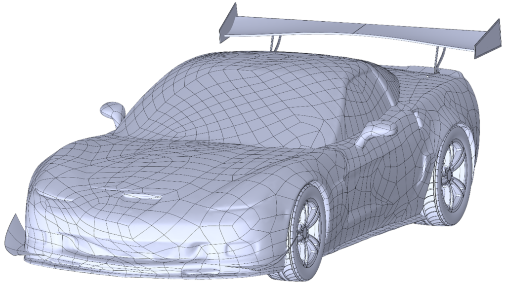
Image 3. The smooth NURBS surfaces generated from the STL mesh in Geomagic Design X.
Fortunately, a common program in the 3D scanner’s toolbelt is Geomagic Design X which can very nicely auto-generate smooth NURBS (non-uniform rational B-splines) surfaces from the STL mesh (see image 3). This process works well for a car’s continuously smooth organic shapes. Beyond auto-surfacing, Design X can also automatically identify areas of poor geometry definition originating from the scanned data and repair those areas. Lastly, all the surfaces can be formed into a water-tight solid body. That solid could also now be brought into SOLIDWORKS as a dumb imported solid to get to the next step in the process of our Corvette getting its wings.
SOLIDWORKS could have been used to make the swoopy shapes that represent the curvy aesthetics of the Corvette – given enough time and with considerable effort. Because SOLIDWORKS starts with a sketch, its strengths in 3D parametric mechanical CAD can become weaknesses when creating organic shapes. After some trial and error—perhaps using a Loft feature, or some other CAD wizardry—a suitable shape might be found.
Having recently used Dassault Systèmes 3DEXPERIENCE in my daily work, I had a feeling that the xShape app would be ideal for achieving my design intent for the canards. Based on sub-divisional (subD) modeling, organic shapes are native to xShape so creating our desired shape should be a breeze.
Image 4. The Collaborative Designer for SOLIDWORKS connector to the 3DExperience platform.
To help with placement of the new wings being designed, the car geometry is brought into the 3DEXPERIENCE platform via the Collaborative Designer for SOLIDWORKS connector (see image 4).
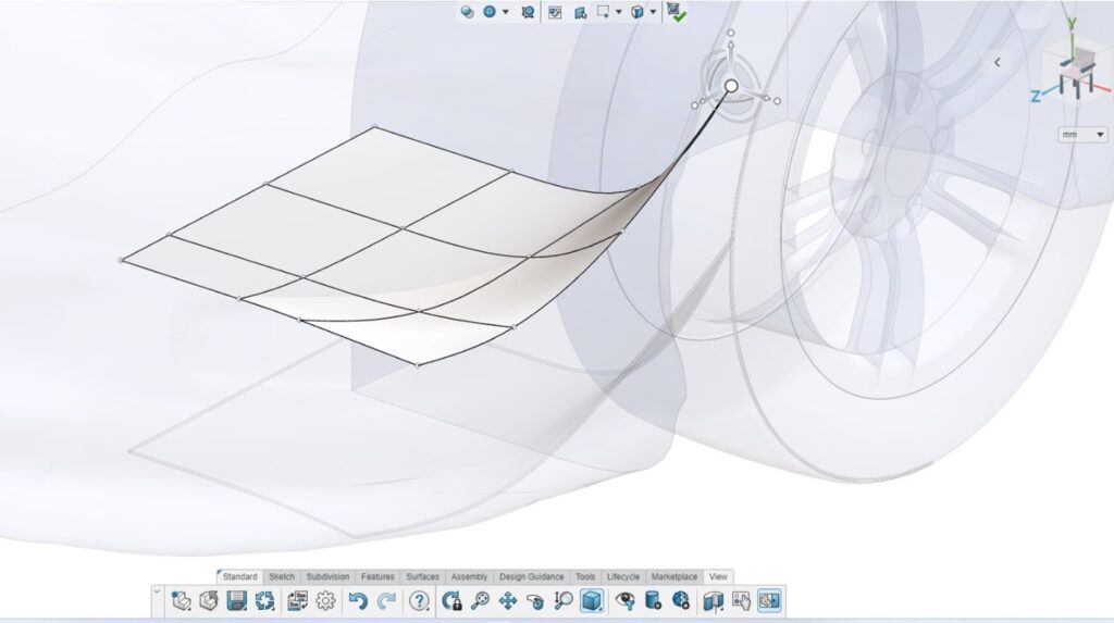
Image 5. The robot triad in the xShape app is used to move the rectangular surface body into place on the car body.
The basis of the canard is a rectangular surface body that can be easily spawned in xShape. Using the translational and rotational operators on the robot triad (see image 5), the surface is manipulated until it is located just aft of the front bumper and before the front tire wheel well. The whole of one edge of the surface is embedded into the car’s body, which will later be trimmed to exactly match the exterior for the attachment lip.
Image 6. The curved canard created in xShape by moving a vertex of the surface body.
Clicking a vertex of the surface activates the robot triad, allowing the point to be moved such that the oncoming airflow will be directed both away from the front tires and into the freestream towards the rear window and spoiler (see image 6). The two edges and adjacent sub-surfaces shared by that vertex become curved and remain continuous; this is the power of SubD modeling.
Placement of the point is based on both experience and judgement, considering various factors such as the vehicle’s weight distribution, the airflow around the vehicle and the desired downforce. A determination for those won’t really be known until CFD simulations are run later. The surface can be thickened uniformly to create a solid body ready for CFD.
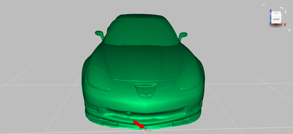
Image 7. The global origin indicated by the red arrow and orientation stays consistent throughout the design process.
From one software package to the next, the overall design intent drove the entire process by keeping the orientation and global origin consistent throughout; in this case, the Z-axis up and the origin placed at the front lower part of the bumper at center, indicated by the red arrow (see image 7). When the curved canard itself is transferred over into the SOLIDWORKS environment, for example, it comes over exactly where it was placed in xShape. The canard is mirrored using the opposite handed option to place the complementary pair on the other side of the car.
Image 8. The completed assembly with the canards and the spoiler ready for CFD simulations.
The rear wing, or spoiler, assembly comes from an aftermarket performance car supplier as a multi-body solid part including mounting brackets, so this additionally gets imported into SOLIDWORKS and placed at the rear of the car. The completed assembly (see image 8) is now composed of all components to be run in the CFD simulations: the scanned C5 Z06 Corvette body, the curved canards designed in xShape and the aftermarket spoiler.
In summary, the overall design process used here consisted of multiple design software tools to facilitate each step of the way based on what program was best suited for the task at hand. It’s similar to having various machines available in an engineering shop, like a saw, grinder, lathe, drill press and router, to bring an idea to life—though in this case, all the tools are digital.
The process started with digitizing the car exterior, post-processing the data to make a water-tight solid body ready for CFD, forming curvy organic shapes with subD modeling, importing an off-the-shelf third-party part and putting them all together for evaluating their combined aerodynamic performance to improve on the original high-performance vehicle. We expect that the aerodynamic modifications to the Corvette will further improve performance measures, such as enhanced handling, increased downforce and overall reduced drag.
In our next article, we will look at the fluid flow simulation of the C5 Z06 to determine just how well the aero parts will perform.
About the Authors

Christopher C. Duchaine is an Elite Application Engineer and has 10 years engineering experience using CAD to design mechanical and electromechanical systems in the industrial equipment industry. He has worked for over 10 years for SOLIDWORKS Value-Added Resellers at TriMech.

Joe Galliera currently is reinventing the future of energy at SJK Energy Solutions. He acquired the nickname Flow Joe while working at SRAC and SOLIDWORKS for 18 years as a specialist in FEA and CFD simulations. He is the proud father of a very creative ten-year-old girl.


