How to Merge the MCAD and ECAD Experience
Internet of Things Products to Drive the ECAD and MCAD Merger
After all, electronics need to fit into these small devices and these small devices need to protect our electronics.With new Internet of Things (IoT) products emerging all the time, more and more mechanical designs will be driven by electronic constraints and vice versa.
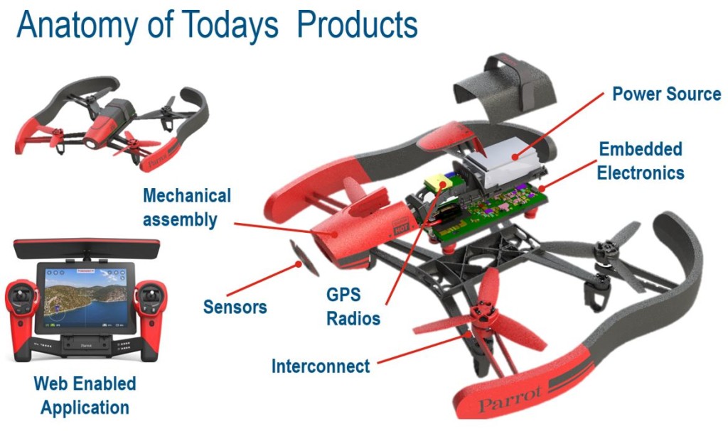
Anatomy of an IoT product doesn’t leave a lot of space for the electronics. (All images courtesy of Dassault Systèmes SOLIDWORKS.)
As a result, “the software we use to design these products, mechanical CAD [MCAD] and electronic CAD [ECAD], need to drive what is happening in the real world,” said Louis Feinstein, product manager at Dassault Systèmes SOLIDWORKS. “Geometry, spacing and tolerancing all have tight constraints in IoT. Blending the MCAD and ECAD makes it easier to design for these constraints.”
The transfer of data between ECAD and MCAD users is nothing new. Various tools use industry standards to translate data from one format to another. However, this data transfer becomes complicated when users have to deal with multiple software products, versioning and metadata issues.
To address these issues, Dassault Systèmes and Altium have teamed up to create the SOLIDWORKS PCB (SW PCB) and SOLIDWORKS PCB Connector powered by Altium. Unlike other MCAD/ECAD communications tools, this new product aims to have one data file. To achieve this, the program employs Altium’s ECAD technology but is branded and operates as if it is part of the SOLIDWORKS system of software.
“We see this product as an ECAD for the design of smart connected devices,” said Aram Mirkazemi, CEO of Altium. “The way these products come together forms a platform for work that would accommodate things that were not possible in the past because of the fences between the MCAD and ECAD worlds.”
What a Unified MCAD/ECAD System Looks Like
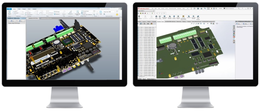
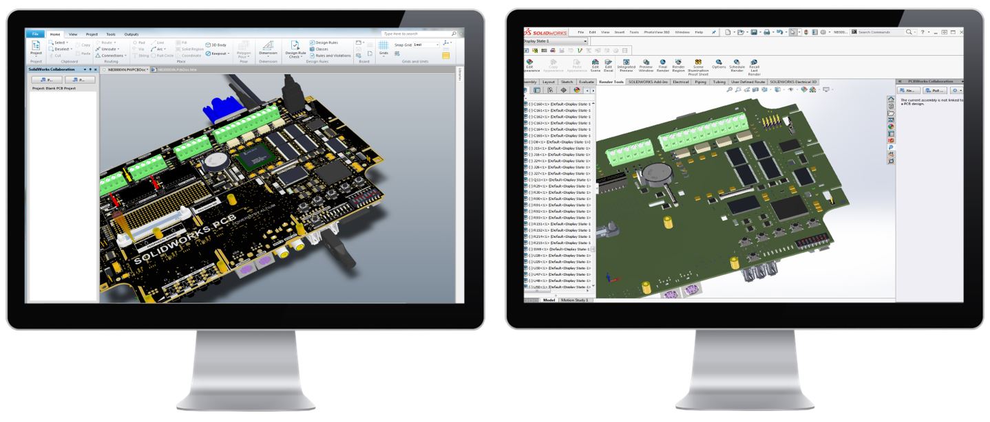
Side-by-side comparison of SW PCB and a converter.
With these tools, users will be able to design their circuit boards with traditional techniques, such as ECAD schematic, routing and layout tools.Feinstein and his team hope SW PCB and the SW PCB Connector will revolutionize MCAD/ECAD integration. He explained that the former is a standalone product aimed at the ECAD market while the latter gives core Altium users the same functionality.
However, whereas these tools are traditionally in separate platforms, SW PCB will make them available in one single environment and user interface (UI). In addition, the software also offers electrical engineers the ability to see their SW PCB designs in a 3D environment. Finally, MCAD and ECAD users will be able to access a shared library of supplier components during their design.
“It will have all the power for the power users,” assured Feinstein. “But the UI changes will make the learning faster as you won’t need to jump between tools. It will all be in one space. The tool also uses minimalistic icons so it’s easy to pick up.”
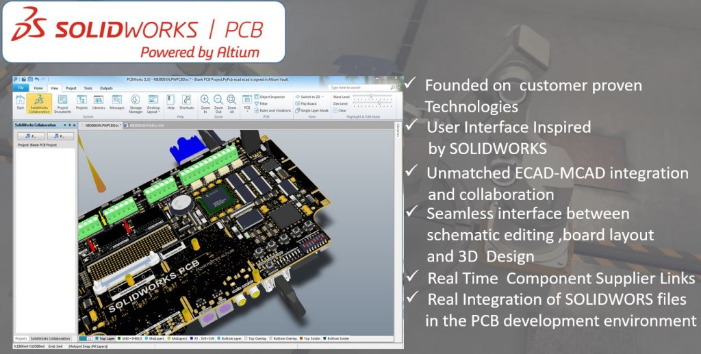
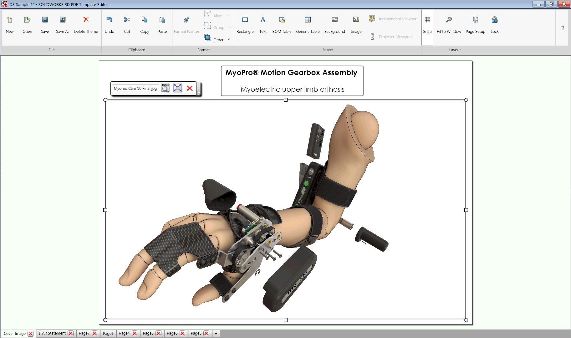
Summary of SW PCB functionality.
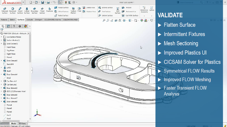
How Users Can Better Merge Their MCAD and ECAD ExperienceSW PCB uses a UI similar to SOLIDWORKS 2016, a release that saw significant UI changes designed to simplify workflows. But given the reaction of the SOLIDWORKS community to the 2016 user interface, SW PCB may want to allow the user to select a “classic” SOLIDWORKS interface in a future release.
How Users Can Better Merge Their MCAD and ECAD Experience
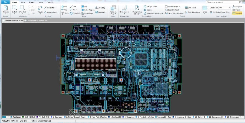
Layout view of ECAD data.
To access the ECAD drawings in SOLIDWORKS, SW PCB users need to push their changes to the mechanical engineer through an imbedded instant messaging service. SOLIDWORKS users can access this service through an included plug-in.“We are not relying on a translator, which allows us to get tighter coupling of the information into one unified data file,” said Feinstein. “We are moving native data between the SOLIDWORKS collaborative server, but it is working in a database. It’s not translated data; it’s the data. And the MCAD and ECAD engineer can access that file at the same time.”
The mechanical engineer has the option to accept or decline the changes. If accepted, the changes are automatically updated into MCAD drawings. If declined, the ECAD drawings are sent back to the electrical engineer.
Once the mechanical engineer is finished with their work, they can send their changes to the electrical engineer through the same messaging process to ensure proper collaboration.
“Traditionally, you would have to do this all with translation type files [IDF, IDx etc.] and generate the final files through a translator,” explained Feinstein. “You don’t need a translator here. So you don’t have to do any extra work.”
Traditionally, users have relied on Windows File Explorer and subdirectories, third-party software or a more primitive “throw-it-over-the-wall” data exchange between electrical and mechanical design teams. While admitting that the SW PCB product data manager may be a little clunky, Feinstein sees a future with SW PCB data management that approaches the highly-integrated and automated data management systems like the ones MCAD users enjoy.
What Are the Benefits of Merging ECAD and MCAD?
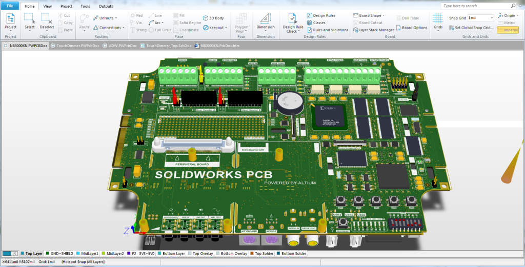
3D view of ECAD data.
“Once you bring ECAD into the ecosystem, we can bring in all the inner layers, materials and geometry downstream,” said Feinstein. “This allows you to do any type of simulation with higher fidelity and accuracy—from thermal to electronic cooling flow and structural simulations.”Since the ECAD and MCAD data is all available in one SOLIDWORKS-compatible file (not Parasolid, but a file format specially created for SW PCB), engineers will be able to bring that data into the SOLIDWORKS system of products.
Feinstein explained that this merger between MCAD and ECAD can open the door to various simulation options that are traditionally hard to produce with ECAD alone. “Electronics simulations typically are done with a 2.5D field solver: methods and moments sliced into integrals,” he said. However, since the ECAD models are now in a SOLIDWORKS-compatible format, the door to native 3D electronics simulations is now open for a higher fidelity model.
The benefits don’t end at simulation. Engineers will be able to use the model-based definition (MBD), tolerancing and inspection tools available from within their MCAD/ECAD model. “Often these tools are associated with MCAD, but now we are blurring the lines between MCAD and ECAD,” said Feinstein.
The Future of SOLIDWORKS’ ECAD Portfolio
Upon its release, “SOLIDWORKS Powered by Altium” will replace Altium’s PCBWorks. CircuitWorks, on the other hand, will still be maintained due to its popularity in the industry. In fact, Feinstein hinted that SW PCB capabilities may be passed on to CircuitWorks whenever possible.
The cost of SW PCB is still to be published. We expect its price to be set at around $5,900, matching the price of SOLIDWORKS Electrical Schematic Professional.
Are you excited for this new program? How often will you be using the 3D ECAD functions? Comment below.
About the Author

Shawn Wasserman (@ShawnWasserman) is the Internet of Things (IoT) and Simulation Editor at ENGINEERING.com. He is passionate about ensuring engineers make the right decisions when using computer-aided engineering (CAE) software and IoT development tools. Shawn has a Masters in Bio-Engineering from the University of Guelph and a BASc in Chemical Engineering from the University of Waterloo.


